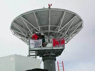
GOES/MARISAT Antenna and RF Building
|
The new station would have more people and more science, and therefore need more communications. Until this point, station internet capability included the GOES-3 satellite link (originally established with GOES-2 and LES-9 satellites in 1993-94), and SPTR, installed in 1997-98. | |
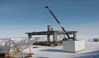
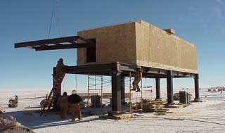
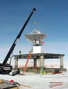 And a bit later on 20 December, here was the big lift, installing the 9-meter dish. The equipment module is already on the platform (JM). | |
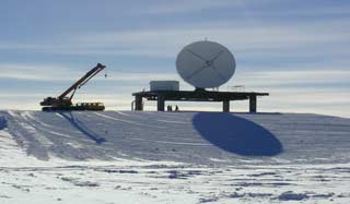
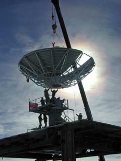 Here is a closer look at the lift, with the dish silhouetted by the sun (JK). |
|
|
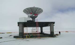
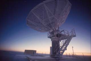
Testing began in late summer and continued...and continued through the winter. In addition to the expected electronics coordination issues, there were mechanical problems with the drive system, the heaters to keep the gears and motors warm, and the grease involved. More extensive maintenance and testing occurred during the 2001-02 summer, and the smaller GOES dish was moved from the roof of the elevated dorm to the antenna platform as seen in the photo below. But it would be another year before the system achieved its design performance objectives. In 2002-03 the feed was replaced, and after subsequent integration and testing, T-1 data rates (1.544 Mbps) were achieved with both the GOES and MARISAT satellites, as well as better automatic control. The following years would bring more drive system problems, the radome installation, system improvements, and the loss of the MARISAT satellite in 2008. 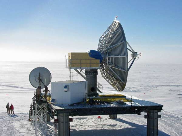 Here is the completed 9-meter antenna along with the GOES backup antenna, as seen a year after completion (January 2002). We are looking away from the station--you can see some of the runway markers in the distance. Also note that an enclosure has been added to help shelter some of the moving parts--not well enough, as it turned out, and in 2004-05 the radome was added (NP). Photo credits: Carlton Walker (CW), Jeff Kietzmann (JK), Jerry Macala (JM), Vik Verma (VV), and Nick Powell (NP) (Nick's photo is from the Antarctic Photo Library. | |
