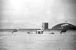
In 1977 we found some old undated negatives from the
construction days. Here is a slide we made from one
of them, probably taken during the 1973-74 summer
...now for the rest of the story!
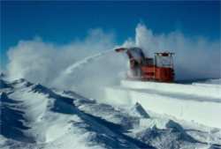
Preliminary site prep began during the 1970-71 season, as you see here (right) a Peter Snow Miller is doing well at processing the dome and utilidor foundations. Unfortunately, these machines couldn't handle the Pole altitude and snow conditions over the long term, and much of the foundations were compacted by running the D8's over them. photo from Gary Brougham
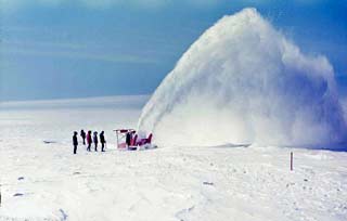
Another view of a Peter Snow Miller at work, probably digging out a trench for the utilidor in the early days. (from the dome erection folder--a trove of station construction photos that I found the Pole common drive during my 2005 winter)
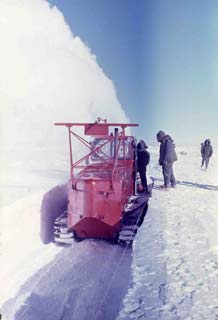
At right, a closer look at the back end of the Peter Snow Miller hard
at work. Not sure if this is a trench for the dome foundation or the
utilidor, but...lots of trenching to do. (from the dome erection folder)
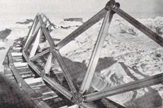
Here is a view of the early construction of the dome base ring from the 1971-72 season (Navy photo, Antarctic Journal (AJ) 3/72). The dome snow foundation was complete on 19 January, and by the 22nd the base ring erection had begun. Very little of the ring actually got built during the first season. However, 80% of the 720' utilidor was completed.
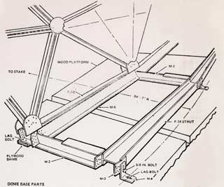
This diagram from the TEMCOR dome erection manual shows the details of the foundation base ring. The differential settlement of the timber pads underneath this foundation caused some of the aluminum nodes and base ring beams to break eventually, these were repaired in 1989-90.
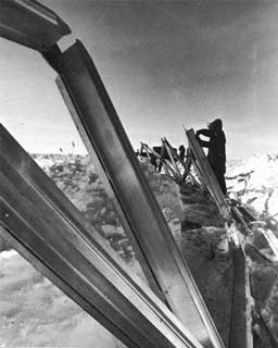
Seabees assemble the lower portions of the dome in 1972-73. Bob Nyden
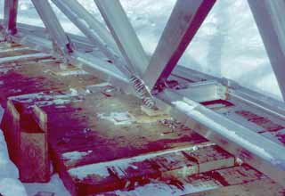
A close look at the base ring assembly in progress in 1972-73. Don't ask me about the purple paint(!) (from the dome erection folder)

The photo at left (courtesy Bob Nyden from a 72-73 cruisebook) shows early construction of the dome ring, while excavation for the utilidor is also proceeding.
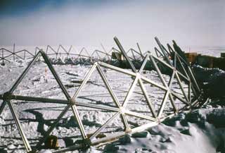 The lower portion of the ring is mostly in
place. (from the dome erection folder) 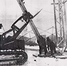
Assembly of the central portion of the dome required a 5-legged central tower to raise the center section of the dome incrementally as it was assembled around its edges. Here at left, the lower section of one of the tower legs is being raised. (Navy photo, AJ 7/73)
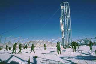
Raising the final upper leg of the erection
tower. (from the dome erection folder)
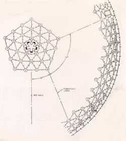
This page from the TEMCOR dome erection manual manual shows the central tower and the initial assembly of the upper portion of the dome. This is a common method to erect domes and radomes--after the base ring portion was erected, the main central portion of the dome was erected from the top down. The 5-legged tower had 10 hand winches which attached to the upper portion, after each ring was added around the circumference, the assembly was pulled up and the next ring installed. After all of the top portion of the dome was constructed, it was raised above the base ring, then lowered slowly and connected to the base ring.
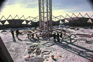
At right, the first center section of the dome is being assembled,
held up by the tower. (from the dome erection folder)
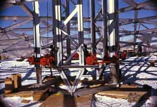
Did I mention that there were ten hand winches? (from the dome erection folder)
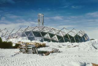
This view from outside the dome shows the central tower supporting the skeleton of the upper portion of the dome, behind the lower portion which has some of the skin panels installed. (from the dome erection folder)
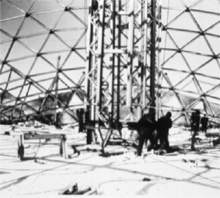
At left, a closer view of the tower, as the raising of the central portion of the dome is underway. (from NSF courtesy Jerry Marty)
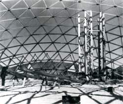
At right, later in the season (Navy photo, AJ 7/73) the dome upper portion assembly has been completed, with its outer edge resting on the snow surface. Here the central tower is being dismantled; portions of it will be erected at 10 equally spaced points around the edges of the upper section, to lift it up to join the lower portion of the dome ring, which is visible in the background.
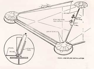
This page from the TEMCOR manual shows how the sheet aluminum dome panels are installed. As you can see, removing the panels is rather difficult (as we found out in 1989-90; also all of the fasteners which connect the nodes (circular pieces) to the beams, are "Huck" fasteners, or aluminum rivet-like connectors which must be ground off to remove. Some of the reasons why nondestructive removal of the dome for reuse elsewhere might be a bit labor intensive.
 Putting in the rest of the node fasteners
(from the dome erection folder)

The last dome beam was installed on 4 January 1973. At left, the dome is fully erected, with panels being installed. The machine parked in the right foreground is one of those Peter Snow Millers (photo from Bob Nyden).
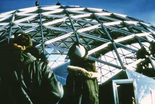 At right is a closeup view of the dome exterior frame with the
panel installation underway. (from the dome erection folder)
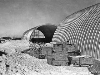
Meanwhile, the arches were happening too....This view from 1972-73 is looking southwest with the construction camp in the distance. (from the Pole Soul mystery negatives we found in 1977)
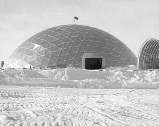
This unique view shows the dome and power plant arch near the end of the 72-73 season. When the dome was designed, NSF didn't know how large the modular sections of the main station structures would be, so the dome design included provisions to remove a portion of the dome wall to get the "vans" inside. This proved unnecessary; all of the components for the interior structures were brought in through this entrance. US Navy photo courtesy Billy-Ace Baker

Here is a construction Jamesway west of the newly completed dome. The emergency exit is visible to the right. US Navy photo, AJ 7/73
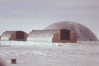 Right: the partially complete power plant and garage arches at the end of the 1972-73 season, boarded up for the winter (this and the next two pictures from Bob Nyden). Right: the partially complete power plant and garage arches at the end of the 1972-73 season, boarded up for the winter (this and the next two pictures from Bob Nyden).
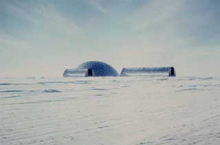
Another view of the 2 partially completed arches at the end of the season.
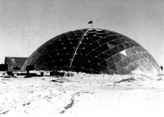
At right is a back view of the dome at the end of the station, taken on 25 January, 1973. Caption: "The new geodesic dome at the South Pole Station, Antarctica. This dome will be used to cover and protect most of the buildings at the South Pole." Photographer EA3 D. Nelson.
| 


