|
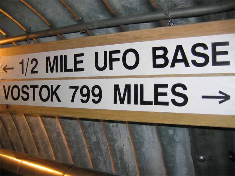
When the new, er, domed station was designed, the plan included a series of undersnow tunnels constructed from egg-shaped corrugated metal arch sections. These tunnels housed the electrical, communications, water and sewer lines between the buildings, and thus were dubbed the utilidor, or "utility corridor." Above is a neat sign that was placed in the branch tunnel to the science building and skylab sometime around 2000 (BS) (photo credits and references are at the end of these pages). For some reason the above-ground piperack between Biolab and GWR at Palmer Station somehow also got dubbed a "utilidor" but I won't go there just now. Anyway, the original tunnels were dug out underneath the dome foundation before the buildings were constructed. | |
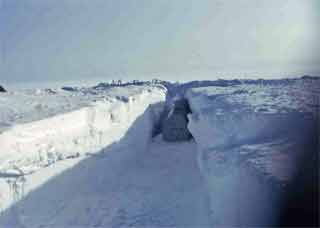
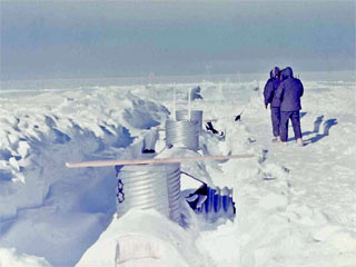
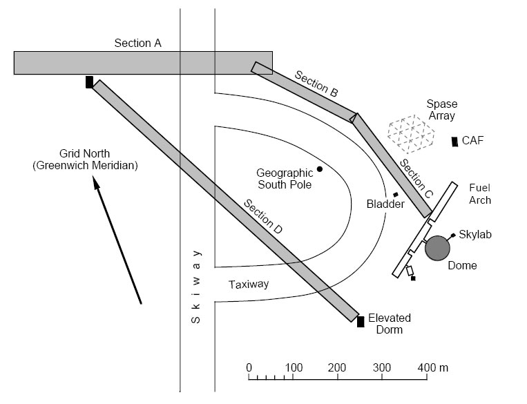
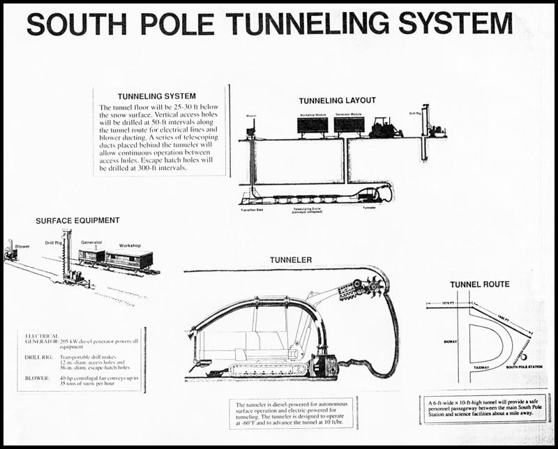
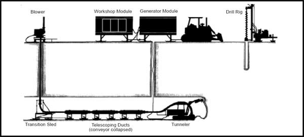
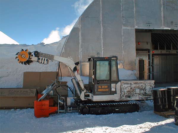
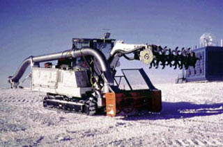
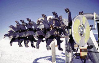
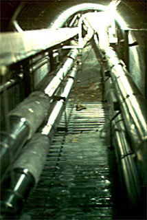 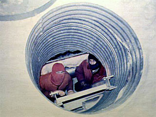 The concept was good...for the time. As for the sewage, the intent was it for it to flow by gravity to the outfall end of the tunnel which was outside the dome southwest of comms. And this worked well for awhile...at left is a view looking in the direction of the outfall...and at right is a shot of Bill Koleto and Ken Gibson looking up from the manhole outside the galley (BS). In 1977 we noted some snow cracking in the floor of the dome over towards comms, this turned out to mark the beginning of what would be ongoing problems with the sewer outfall. First...that end of the station was being pushed down by the big snowdrift on the downwind side of the dome. Secondly, the snow above the sewage bulb was starting to settle. And finally, no one had really figured out the lifetime of this first sewage bulb, which of course was rapidly filling up. Only 2 years after my first winter, in 1979-80, there were attempts to level the sewage outfall within the utilidor, but the sewage bulb eventually filled up and started to flood the end of the utilidor. A lift shaft was installed, and the first of several lift station pumps was constructed to pump the sewage up out of the utilidor to an elevated gravity pipeline which flowed to a new sewage bulb. The lift pumps were replaced several times with more serious grinder pumps that could deal with sanitary napkins. Anyway...this scenario would eventually set the stage for the next generation of utilidor tunneling at Pole... In January 1992, CRREL was tasked by NSF to develop a tunneling system to be used in conjunction with the new station. Accordingly, their first task was to do ground-penetrating radar (GPR) studies of the intended tunnel route. They did this during the 1992-93 summer (above, CRREL 1995). But it seems that the intended tunnel was to provide a passageway for utilities and pedestrians from the station under the skiway to the new science facilities under construction in the dark sector. Hence the survey routes in the above diagram...it seems that environmental studies were conducted, and the project almost went ahead, before all discussion of it suddenly stopped. Meanwhile, below is a preliminary diagram indicating the intended configuration of the tunneling machine, and the planned utilidor route to the dark sector (CRREL, 1996). The machine consisted of a modified Melroe Bobcat excavator with a snowblower mounted on the front for chip removal. The bucket was replaced with a hydraulically powered rotating shaft with cutting arms for machining the tunnel. An electrohydraulic power pack was installed behind the existing diesel engine, this was driven by a sled-mounted Caterpiller 180 KVA (at altitude) 480v 3 phase generator. The chips were conveyed from the snow blower to the surface via horizontal and vertical round duct, propelled by a 50 HP fan which (in the final configuration) could move 2500 CFM--including about 8 lbs/sec of snow. The system included a Simco drill rig to produce the 1'-diameter holes for the power cables and snow blower duct, as well as 3'-diameter round escape tunnels. The system was tested in some snowy areas at CRREL, and shipped south in August 1993, but for various reasons it did not actually make it to Pole until January 1996, where some preliminary testing was conducted. | |
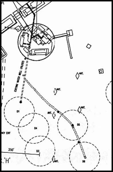
By the time the machine made it to Pole, the original project goal (the tunnel to the Dark Sector) had been overtaken by events, and the new "proof-of-concept" task would be to construct a tunnel between the existing utilidor sewer outfall--the straight dotted line in the drawing at right--and a new sewer bulb, so as to provide a gravity flow system. This tunnel is the curving solid lines branching down and to the right. While the 1996-97 testing resolved some significant mechanical problems, the test bore ended up only about 25 feet long--approximately the length of the machine. Things were more successful however the following season, when the new 380-foot tunnel was completed. It was started at the outfall end and dug uphill curving towards the utilidor. The basic tunnel configuration--6' wide x 10' high, was typical of all of the tunneling operations. Below are several photos of the tunneling operation (CRREL 1999A). |
 |
|
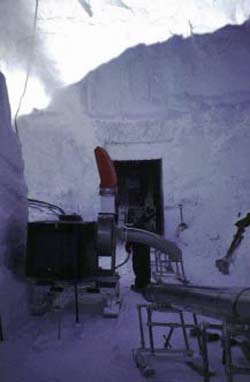
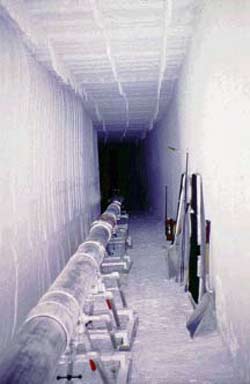
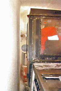
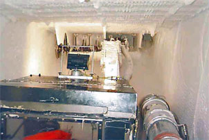
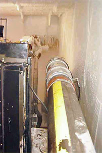
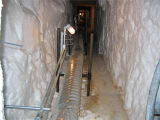
Above left, the start of the tunneling operation, before it is necessary to have the exhaust duct vent the chips to the surface through a vertical hole. Middle, the exhaust duct extends through a completed portion of the tunnel, which...at right, is done. 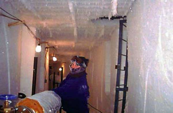 And before the end of the 1996-97 summer, the sewer piping was installed and put in service. Behind the insulator is one of the escape hatches (CRREL 1999A) | |
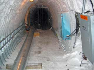 The south end of the original utilidor; the new CRREL tunnel branches off to the left, and straight ahead through the iron gate leads down to the original 1970s outfall. The blue panel on the right is a control box for the lift station that used to be at the bottom of the vertical shaft to the right (BS). | |
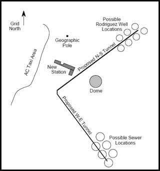
After the successful tunnel in 1996-97, the equipment was again returned to the US for modifications and repairs, and it was deployed to McMurdo for testing in 1997-98 and 1998-99. Later that season it was flown to Pole for further testing, after which there was a symbolic turnover of the keys to the contractor ASA, represented by John Wright and John Penny--these folks would take over the operations for the last 3 full seasons of real work...the sewer and water tunnels for the new station. Meanwhile, CRREL did another GPR survey for these tunnels--at that time it was planned to have 2 sets of tunnels and wells--one north of the arches for the water wells, and a second branch south of the dome for the sewer bulbs (diagram at right, CRREL 1999B). |
|
| And now for the rest of the story...the new station sewer/water tunnels... | |
