2010-11 Photos - Askaryan Radio Array
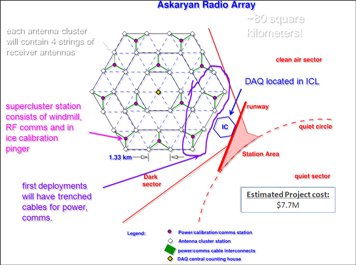
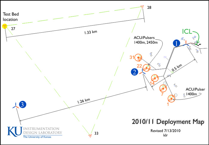
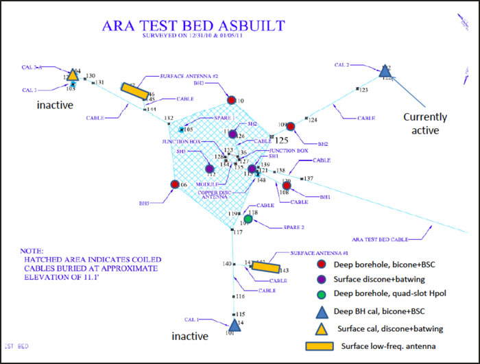
Now that IceCube is completed...some members of the South Pole Users Committee (SPUC) speculated at their 2010 meeting that the Pole summer population could drop from the current 250+ levels. Not so...more big projects are in the works...such as the Askaryan Radio Array (ARA), above (the circa 2015 UW project home page). This project saw its first system test components installed at Pole during the 2010-11 summer. In fact, the MRI (Major Research Instrumentation) proposal document to NSF (which is no longer online) stated, "Over the last five years, IceCube has been the dominant engineering activity at South Pole; ARA will take over this role as IceCube construction winds down" (2). Another earlier version of the map is here (7). 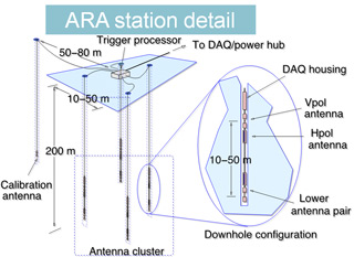 The project envisions an 80 sq km array...arranged in a hexagonal shape similar to IceCube, but much larger as you can see. Each large triangle ("super cluster") is to have a central power station and controller hub with a wind turbine and a photovoltaic panel...the 3 corners of each triangle will each have a cluster of four 200m drill holes ~6" in diameter to house the detectors, and another for calibration equipment (right) (1). Each hole will contain two pairs of horizontal polarization (Hpol) and vertical polarization (Vpol) antennas. Each cluster will also include two surface fat-dipole antennas. The clusters will be wired back to the central super cluster controller and power station. Each triangular super cluster will be powered independently and transmit its data back to the IceCube laboratory (ICL) using 925 MHz wireless communication (the clusters closest to the ICL will be hard-wired to that building for power and communications). So why do we need another neutrino telescope when IceCube is already the world's largest? Briefly, the ARA project, like IceCube, are both looking for neutrinos from high-energy systems in the universe. IceCube uses digital optical modules, which detect light emissions from neutrino interactions with the ice. ARA will use radio antennas to detect nanosecond-long radio pulses. IceCube is optimized to detect lower-energy neutrinos such as those associated with supernovas; ARA looks for the highest-energy neutrinos. These are believed to be produced by ultra-high-energy cosmic rays, perhaps emanating from supermassive black holes in nearby active galactic nuclei. IceCube utilizes the Cherenkov effect, where charged particles moving faster than the phase velocity of light can emit light radiation. ARA utilizes the Askaryan effect, whereby charged particles can similarly emit radio or microwave radiation. The high energy of these particles means that a much larger array is required than IceCube. So...what is going on, and what happened at Pole in the 2010-11 season? The project is, like IceCube, a collaboration, with a number of the same major university players--Wisconsin (UW), Delaware (UDel), Kansas (KU), Maryland, Hawaii, and Brussels. The project was funded for a 3-year preparatory/test period...the schedule (assuming successful testing and full funding) calls for continued testing over the next few seasons, with the final shipment of instrument clusters to Pole scheduled in time for the 2014-15 season. In 2010-11 there were two separate test operations underway...first, a team from UW experimented with drilling and cabling and installed test cabling and instrumentation strings at the "test bed site"...and a team from KU who deployed three ~1kw wind turbines with associated control boxes, batteries, and communications equipment...at the locations seen below(7): The red numbered circles denote the easternmost IceCube strings in this area...the three wind turbine/power units were installed by KU at the blue numbered circles, and the UW folks installed the some of their test instrumentation at the "Test Bed Location" in the above diagram. Below: an as-built detailed layout of the test bed (1). First, the UW activity, much of which involved trenching and drilling, some of it assisted by the IceCube drillers... | |
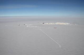 Above, an overall aerial photo...the main station is the large structure in the center; the test bed site is in the right foreground (3). |
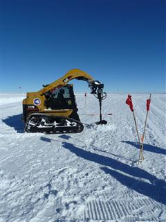 Some of the test receivers were put in shallow holes drilled with this auger (4). |
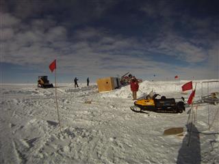
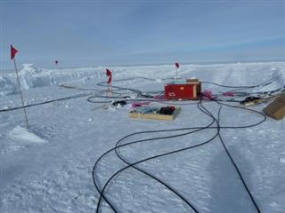
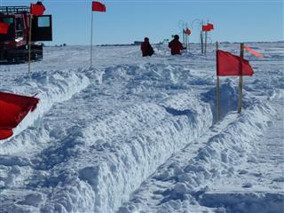 Here can be seen some of the trenching...and above-surface antennas. The main station can be seen in the distance (4). |
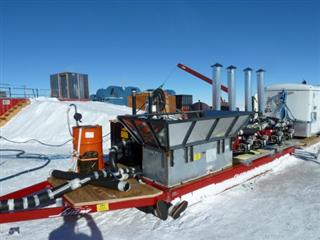
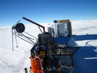
 Other holes were created with this hot water drill...the same principle as the main IceCube drill, but much smaller...the heaters and pumps were mounted on a sled (4). |
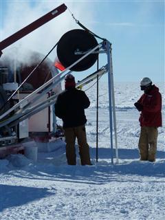 A closeup of the "drill tower." This hot water drill can produce a 200m hole in about half a day. The deepest holes in 2010-11 were 160m; in the operational sites will be 200m deep (4). |
 This drill was actually adapted from the IceCube trenching equipment (4). |
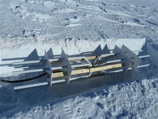
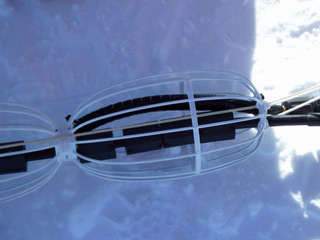
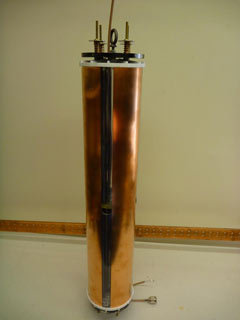 A quad-slot cylinder Hpol antenna. This was installed in one of the test bed boreholes (9). | |
 Another view of the bowtie. After testing, the cylinder Hpol antenna (above) was selected for the next phase (9). | |
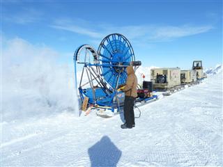 Another item to be tested was the RAM (Rapid Air Movement) drill. It is powered by 3 air compressors, these spin a cutting head, and the air blows the chips up and out of the hole (4). |
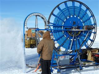 Here's a closer view of the drill sled itself. This air drill produces a dry hole that doesn't need pumping out (4). |
| Perhaps the most important and most difficult (and most highly difficult) aspect of the project at this phase is the wind power system. After extensive study and evaluation of more than a dozen manufacturers, the Kansas team selected three different ~1KW wind turbines for installation. They all had a rotor diameter between 2.5-3 m, similar general specifications but lots of differences in the details. All 3 of the machines received modifications such as replacing the standard bearings and bearing grease. For each, the vendor's standard tower system was used. | |
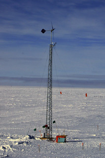 This one is a Raum 1 KW machine, mounted on a 50' lattice tower which has four steel guy wires. This unit was installed at Site 1 (map above); it was raised using a 10' gin pole and a Pisten Bully. A single anemometer was mounted just below the turbine to monitor performance vs wind speed (6). |
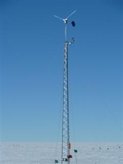 Here's a closer view of the Raum. These turbines are manufactured in Saskatoon, Saskatchewan (5). |
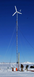 The 1KW Hummer unit, mounted at Site 2 on a 50' monopole with three sets of four steel guy wires. This assembly required a Cat 853 tractor to raise because of its weight. A single anemometer is located just below the turbine, along with a Yagi antenna aimed at the ICL. Hummer was located in Fort Wayne, Indiana although their website disappeared in 2012 (archived website from 2012) (6). This turbine totally failed during the 2011 winter; it was to be replaced in 2011-12. |
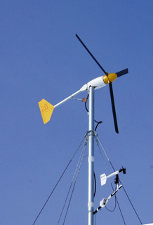 This is a Bergey XL.1 model, mounted at Site 3 on a 60' monopole with integral 20' gin pole and three sets of four Kevlar guys. It was raised using a Pisten Bully. Bergey's main plant is in Norman, Oklahoma, with a subsidiary in Beijing. This installation included three wind birds. (6). |
|
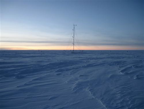
Above...the Bergey turbine as seem at the end of March 2011 (8). As for the turbine testing in 2011, so far all was not well. One of the machines broke down early in the winter...and one of the other 2 became incommunicado--its comms cable was apparently cut at some point, so the data had to be retrieved from the memory card manually. There are lots of other things to be evaluated...performance of batteries, electronics, cabling...shielding/grounding/static electricity and interference issues--between different components of this project and between ARA and other projects on station... insulation/ heat dissipation...communications and software. But overall the ARA testing went well, to be continued in 2011-12. References (the numbers refer to the specific sources of the photos/figures; all of these references were also used in the development of the text on this page): (1) "ARA: The Askaryan Radio Array," a report presented by Kara Hoffman, University of Maryland, presented at a 4-5 April 2011 conference "Astrophysics from the South Pole: Status and Future Prospects" in Washington, DC. (2) The MRI proposal is no longer online. The current ARA publications page is here, and the updated NSF award page (with additional references) is here. (3) Aerial photo from the USAP photo library (by Robert Schwarz). (4) Blog by Dr. Mike DuVernois, who spent time at Pole in 2010-11 working on the test bed installation. (5) The "gallery" section of the Askaryan Radio Array UW project web site. (6) Photos provided by Mike DuVernois. (7) The original University of Kansas document page http://www.idl.ku.edu/ARA/AARPS/Documents/default.aspweb is no longer available. The deployment planning document containing the older site plan and 2010-11 test bed deployment map "APS Report 20 May 2010" is here. (8) Blog entry by Marco Tortonese, 2010-11 CUSP science tech. (9) "Design and Initial Performance of the Askaryan Radio Array Prototype EeV Neutrino Detector at the South Pole", August 2011. by members of the ARA Collaboration. Also going on in the dark sector: the repair of the South Pole Telescope. | |
